2007-01-28
Ny svensk motor - NB 5.
Sept 2005 åkte Octan-maffian till New York och körde och där träffade vi båtåkaren Jim Allen och fick se hans fantastiska källarverkstad. Han gör allting själv - motorer, bromsbänkar osv. Hans 15 cc. motorer har vevhus i stål, vilket han nämnde var överlägset ( i bromsbänken ). Red tog då upp den 50 år gamla tanken att se om jag kunde klara att göra en egen motor. 1958 - 1959 vände jag en Super Tigre med hjälp av en liten Hobby - Mat och den flög jag 205 km/h med på Modellsportens Dag med hjälp av nitro och pen-bladder. Baksug och fiberdisk. Jag förstod då inte hur lovande den var och att det var rätt väg. Sen hade jag under många år inga maskiner tills jag vid pensioneringen skaffade bra sådana och till VM 2004 vände jag en Novarossi 3.5 som visat sig gå bra. ( 2a på VM ). Så nu var det dags att se om jag kunde klara att göra ett eget vevhus åxå. Inte för att det behövs, NovaRossis vevhus är mycket bra, men för att ha kul. Som bergsklättrare som tillfrågas " Vad har du där uppe att göra " och de svarar " Därför att berget står där ".
Målsättningen var att se om det går att på ett enkelt sätt för en hobbyist att göra en motor i ett exemplar. Jag tittade runt på vad som har gjorts och de som har utvecklat sina motorer bäst är team-racingflygarna och gamle team-flygaren Metkemeyer med sin pylonmotor Profi 40. Mats Böhlin med sin MB 10 har lärt sig göra motorer inom team - racingen. Efter att ha gjort några vevhusprototyper, stod det klart - som en Hornet, delning mitt på - var en bra modell, fortfarande 60 år senare. Problemet med vevhus är att göra det viktigaste rätt - nämligen utformningen av överströmningskanalerna. Genom att dela här kommer man lätt åt att fräsa kanalerna i en enkel fräsmaskin. Det är ett enkelt koncept för en hobbyist att göra en motor med stor tidsinsats - men inte så rationellt för masstillverkning. Att vevkullagren ska sitta i stål är helt klart, samma utvidgningskoefficient som kulringarna och stål har betydligt högre hållfasthet än alumin-legeringar. Jag har använt automatjärn som är mycket lättbearbetat och nitrokarburerat, vilket ger en mycket hård yta. Självklart var ju att sätta motorfästena där de ska sitta, två vid yttre kullagret och två mitt i vevhuset. Cylinderdelen är gjord i lågexpansions-al-legering.
Genom att göra en 5 cc. motor kunde jag använda Novarossi 4.6 foder,kolv och stake, men genom att öka slaget kunde jag få fulla 4.95 cc, vilket novarossis vevhus svårligen har plats för. Insuget Zimmerman med lågfriktionsplast på utsidan. Det skall bli mycket intressant att se om jag kan få fart på denna metallklump i vår, för att prova det måste givetvis en särskild bil byggas, vilket pågår. Nils Björk.
2007-03-09
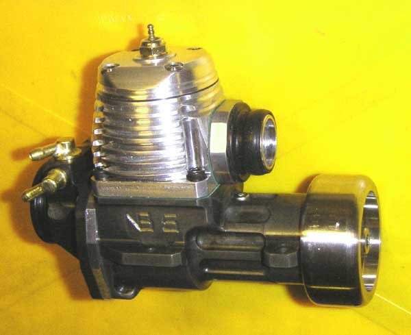
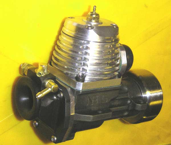
NEW TETHER CAR ENGINE – NB 5 cc.
In the Octan Tether Car
Club in Stockholm we have been playing around with model engines and working
together for 60 years ( diesels, ignition, glow ) and modifying engines on the
market and making own engines to get ( hopefully ) more power and speed. The
best packaging for our tether cars is an engine with the exhaust on the crankshaft
side. There are some wonderful engines for radio cars, but they have crankshaft
air intake, which we think has a gas restriction and weak crankshafts for our
purposes and also there is not many sizes for our old-fashioned classes. Our
market is much too small for commercial engines, so the choice of good engines
for tether cars is very restricted.
When we make our conversions
or engines we have a big advantage over the commercial firms, we can make our
engines with disregard of time-cost. We can compensate our small resources with
best design of every metal or plastic piece and put many labour hours in them,
whereas the professionals have to produce every piece in many numbers and at
moderate cost to be competitive on the market.
One solution has been to
“turn around” mass produced engines making new front housing, crankshaft
and rear induction with drum or Zimmerman disk. Some very successful conversions
have been done lately with the fantastic Novarossi engines 3.5 cc and 4.6 cc.(
Falk, Ek, Bjork ). But the design of crankcase limits the design possibilities
for our cars. Radio engines are designed for power with a relatively broad throttling
band and moderate fuel consumption, whereas we want max. power only and have
use for more peaky and higher power curves with no regard for fuel consumption
or cooling, as we run for a few seconds only. From Bohlin with his MB 10 cc.
and his previous team-race engines we know that making cast crankcases is a
major undertaking: to make a master form in steel and casting at a highly specialised
foundry. So when we visited speed model boater Jim Allen,s wonderful workshop
in New York at GP 2005 I started to think about a simple way to make crankcases
in very small numbers within the walls of my workshop. Jim Allen makes his own
15 cc. engines with steel crankcases shaped from billets.
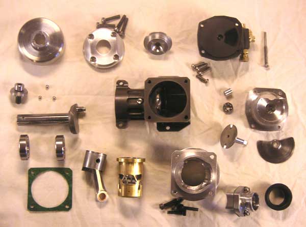
A conventional crankcase
is the house for all parts and is simple to machine except the transfer gas
passages. How to make them? The time honoured method of splitting the crankcase
horizontally is one solution that Hornet and many other engines had 60 years
ago and the Metkemeier Profi 40 pylon engine and Lothar Hentschel combat engines
and lots of team-race engines in recent times. They also had integrated cylinders.
That is essential for good cooling, it is not so important for tether cars,
we cool engines with lots of methanol. If you split crankcase horizontally it
is easy to get at and machine the transfer passages. So I built some crankcase
models and after 5 or 6 the shape was clear. The crankcase ball bearings should
be in a steel housing to get the same thermal expansion for good ball fit at
all temperatures, so the logical thing is to make the lower part in steel. 2
hybrid ball bearings for crankshaft is used: 10 – 22 mm. Steel is also
much stiffer than any aluminium, but has a weight penalty of around 125 grams
for this engine. That is too much for model flying, but axceptable for our tether
cars. Also acceptable is the low heat transmission. I used “automat iron”
1914 that is very easy to machine and surface hardened, nitro-carburated. The
engine mounts were placed where they should be, at front bearing near flywheel
and in center of crankcase. Team-race engines have had that layout for many
years.
Generally two-stroke racing
engines are all about metalurgy. The cylinder housing has to have good heat
transmission and have a low rate of heat expansion, so is machined from low
expansion silicon aluminium alloy. Here the transfer passages are easily milled
and also new housings to experiment with transfer passage shape and dimensions.
Hand finishing of the the very important shape was home territory to an old
dental surgeon. Inside this first engine is a Novarossi 4.6 cc. cylinder and
piston. Novarossi parts are made to a very high standard. Rear intake has a
floating Zimmerman disk on a shaft with 2 ball bearings 4 – 9 mm and low
friction plastic outer housing. Flood-off stopping system is used, so important
for piston life. Later an centrifugal exhaust valve will be made to enable old
men to horse car up to peaky power curve, maybe even myself.
This engine has not yet
run at all, so summer 2007 will be spent trying to sort out the design and fit
mistakes in a new car now being built.
Measurements.
Bore 18.35 mm.
Stroke 18.8 mm.
Comp volume 0.35 cc.
Standard tether car timing. Exhaust 195 ° Transfer 135 °
Intake opens 35° after bottom. Closes 65 after tdc.
Intake dia 12 mm.
References.
The FMV story. Rob Metkemeyer and Enrico Flores. Aeromodeller 1979. April-May-June.
Profi home-page closed. Pity.
www.control-line-team.de Lothar Hentschel combat engines.
Nils Bjork